Applications
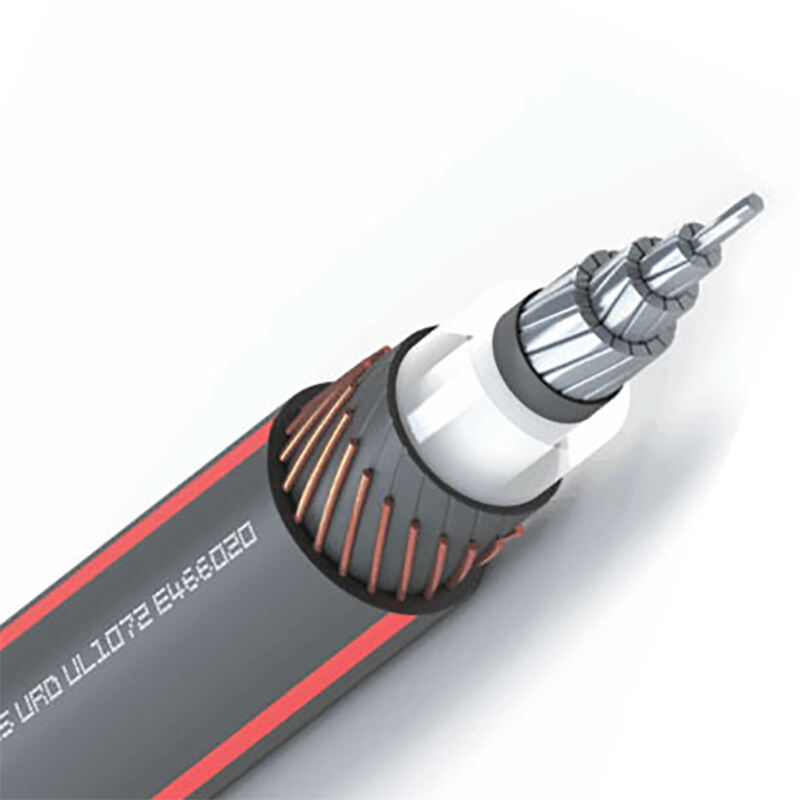
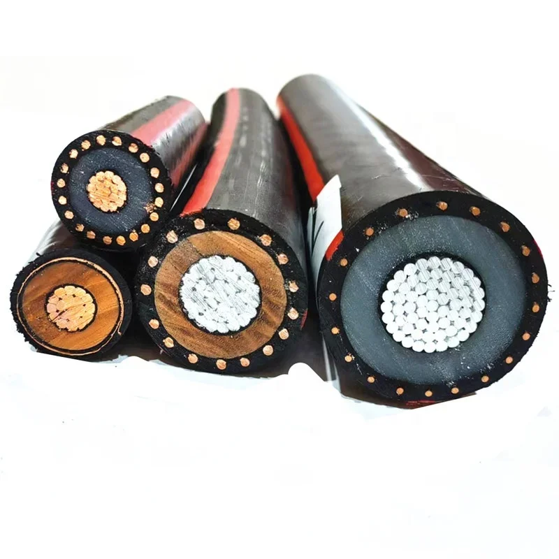
5-46 kV URD Cable (MV-90/MV-105)Underground Residential Distribution Cables are intended for use
in dry or wet locations for distribution of single or three phase medium voltage power. Suited for use
in wet and dry areas, conduits, ducts, troughs, trays, direct burial, sunlight, and where superior electri
cal properties are desired. These cables are capable of operating continuously at the conductor tem
perature not in excess of 90°C for normal operation. 130°C for emergency overload, and 250°C for short
circuit conditions.
Standards
• UL1072 Medium-Voltage Power Cables.
• ICEA S-94-649 Concentric Neutral Cables Rated 5 - 46kV.
• AEIC CS8 Specification for Extruded Dielectric, Shielded Power Cables Rated 5 through 46 kV.
• CSA C68.5 - Primary shielded and concentric neutral cable for distribution utilities.
Features
a. Voltage Rated voltage (U):
5~46 kV
b. Working temperature:
-40ºC or -25ºC MIN, 90ºC or 105 ºC MAX
c. Performance:
Min. Bending Radius during Installation : 20xD
Min. Bending Radius Fix installed : 15Xd
Sun resistance
-40 Degree
Optional
• Voltage: 5KV, 8KV, 15KV, 25 KV, 28 KV, 35 KV, 46KV.
• Insulation Level: 100%, 133%, 173%.
• Conductor: Copper, Aluminum, Aluminum Alloy AA8000Series.
• Insulation material: EPR (UL Certification ONLY)
• Copper Concentric Copper Neutral: Full Neutral, 1/3 Neutral, 1/6 Neutral, 1/8 Neutral, 1/12 Neutral.
• Screen: Copper Tape Shield.
• Jacket: XLPE (UL Certification ONLY) or PVC.
 UV Resistance
 Medium Voltage
 Working Temperature 90℃
URD Power Cable-AL TR-XLPE 15 kV 100% 1/3 Concentric Neutral XLPE (International Unit System) Range and Dimension
All dimensions are nominal and subject to normal manufacturing tolerances.
| SIZE AWGMCM | Nominal conductor diameter | Nominal insulation thickness | Nominal diameter over insulation | Strands No. | Strands diameter | Jacket thickness | Jacket Diameter | Weight |
| AWGMCM | (mm) | (mm) | (mm) | - | (mm) | (mm) | (mm)* | (kg/km)* |
| 2 | 7.0 | 4.45 | 17.0 | 6 | 1.29 | 1.40 | 24.2 | 602.0 |
| 1/0 | 9.0 | 4.45 | 18.9 | 6 | 1.63 | 1.40 | 26.8 | 782.2 |
| 2/0 | 10.1 | 4.45 | 20.0 | 11 | 1.29 | 1.40 | 27.2 | 839.8 |
| 3/0 | 11.4 | 4.45 | 21.3 | 14 | 1.29 | 1.40 | 28.5 | 956.9 |
| 4/0 | 12.8 | 4.45 | 22.7 | 11 | 1.63 | 1.40 | 30.6 | 1,127.1 |
| 250 | 13.9 | 4.45 | 23.8 | 13 | 1.63 | 1.40 | 31.7 | 1,256.0 |
| 350 | 16.5 | 4.45 | 26.4 | 18 | 1.63 | 1.40 | 34.8 | 1,591.2 |
| 500 | 19.6 | 4.45 | 29.5 | 16 | 2.05 | 1.40 | 38.8 | 2,069.3 |
| 750 | 24.1 | 4.45 | 34.4 | 15 | 2.59 | 2.03 | 46.0 | 2,994.6 |
| 1000 | 27.8 | 4.45 | 38.1 | 20 | 2.59 | 2.03 | 49.7 | 3,699.1 |
| 1250 | 31.2 | 5.59 | 43.9 | 20 | 2.91 | 2.03 | 56.9 | 4,748.8 |
| 1500 | 34.1 | 5.59 | 47.3 | 24 | 2.91 | 2.03 | 60.2 | 5,489.6 |
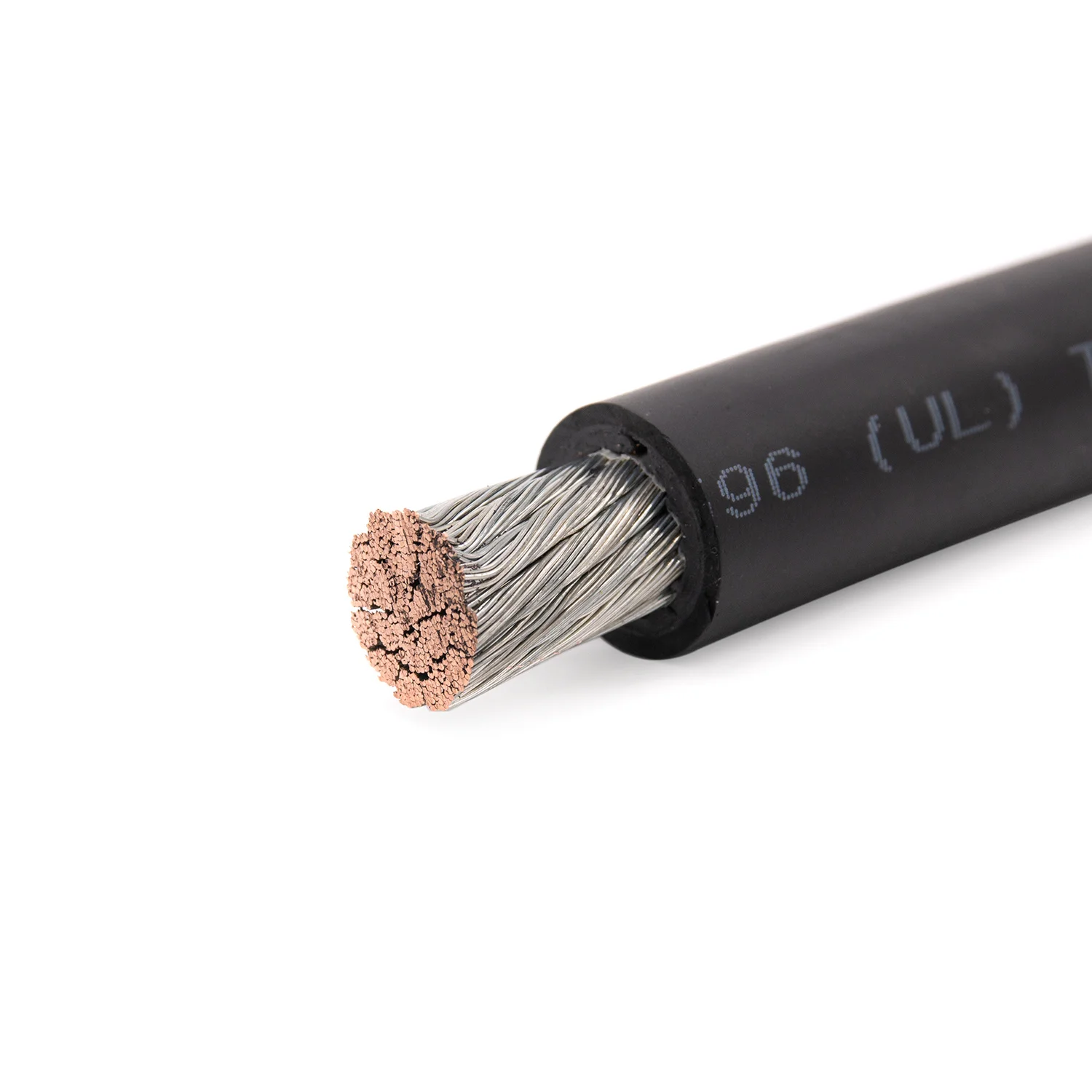
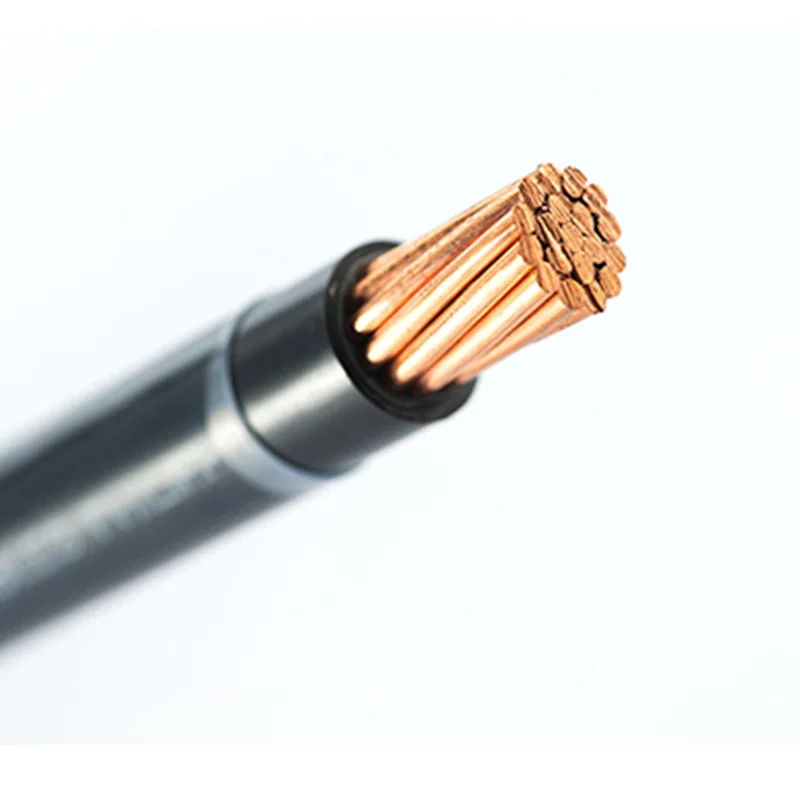
1.Conductor: Solid or Class B compressed concentric lay stranded 1350 aluminum or Copper conductors, Conductor moisture block (optional).
2.Conductor screen: Semi conductive extruded layer.
3.Insulation: Tree-Retardant Cross-linked Polyethylene (TR-XLPE).
4. Insulation screen: Semi conductive extruded layer, Easy strippable.
5. Neutral: Helically applied, annealed, solid bare copper wires.
6. Outer sheath: Sun resistant Linear Low Density Polyethylene (LLDPE) sheath, extruded to fill spaces between neutral wires.